Friday, December 17, 2010

Insulation, Old School: Wax Impregnating Maple

Apologies for the long gap. We are back!

Here's a challenge. Making a good custom-built insulating panel in 1910, without use of asbestos, custom ceramics, or plastics.

The great minds of the age started with wood. Tests were done and it was found that maple, a hardwood, was the best combination of strength, workability and a natural insulator. Except, of course, when it was wet. And wood is always somewhat wet. If you dry it out entirely, it cracks, and in any case, reabsorbs moisture from the air over time.

The idea was struck to use paraffin wax to offset the water. But how? Even if you melt it on, there's still water within the wood.

Experiments were tried with VPI (vacuum pressure impregnation). In this, the unit is dipped in resin, set in a pressure vessel, and a vacuum is drawn. Water boils at about 75 degrees F in a vacuum, so it boils off, the vapor taken in by the vacuum pump. There is literally nothing in the voids, so when vacuum is released (and shop air pressure applied), the resin is sucked into the voids. It's a great theory, it works on metal machines like traction motors. But alas - not wood!

As it happens, liquid wax is happily above the boiling temperature of water. So of course, they had tried simply immersing the wood in hot wax. Above 212 degrees, the water boils off nicely, replaced not with a void, but water vapor. When it cools, this vapor condenses to a tiny amount of water, creating a vacuum that should draw in the wax. Assuming the wax had not turned solid!

In the early days of electric equipment, a great deal of testing had been done on this. They examined wax saturation and insulation quality. With help from the railway preservation community at large, BAERA volunteers had done some research on this.

It turns out there was a very particular pattern of temperature control that was required - heating to high temperature to drive off water, then a lower temperature to allow wax to absorb. The sequence took several hours.

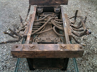
It was within the range of a common (nowadays) electric skillet. The board barely fit! Here we see it at the end of the cycle, the wax re-frozen.

One might look at the picture and think: "OK! Turn it back on, come back in 20 minutes, and fish the board out of the wax!" No. After it was out, the wax would flow out of the wood. In fact, the board must be removed with the greatest care - the wax can be barely softened, and heated with spot heat from a "hair dryer" just enough to wipe the excess away.

The wood has already been machined (drilled). This was a product of careful and repeated fitting to the car. Even with the refinement of these techniques, wax impregnation is far from complete. Machining afterward would have exposed areas of poor penetration.

Monday, June 21, 2010

1005 in repose


Here is SN 1005 parked outside Carbarn 3 for Member's Day. The lower panels are being prepped for paint. The other side is already painted. The car looks good!

What's going on with 1005? First, a complex repair on the brackets which hold up the radial coupler - a lot more on that job is coming. Second, the seats are being sent out for re-upholstery.

Why does it look so good while being parked in the dusty shop? It's kept under plastic. Here you see ropes set up to lift the plastic off the car.

Friday, May 28, 2010

Video of early shakedown run

Last month the car was operated on its own, for the purpose of turning the car around and doing testing of the propulsion system and brakes.

A video of excellent quality was captured, and is located here.


Tuesday, May 11, 2010

Overhauling the brakes

Let's review some earlier work. Many of the components of 1005's brake system have enjoyed an overhaul. Now we get a glimpse of the teardown of the brake cylinder. No, it hasn't been since 1956. You can see in the picture below, the innards of the cylinder.

Center is the piston itself, which moves inside the housing. The plate above it clamps a large rubber gasket. You can see the gasket on the edge of the picture being held by a volunteer.

Upper left is the non-pressure head of the cylinder, also viewable on the left side of the piston in the picture above. As you can see, it guides the piston and gives the spring a place to nest. The spring is a return spring, which assures the piston returns to its seat when pressure is released. Among other benefits, this also protects the piston shaft from the weather.

A hand powered forklift was used to lower the relevant sections from the car - as they are heavy. Parts were cleaned and painted, gasket renewed, and reassembled and returned to service.


Thursday, April 15, 2010

IT RUNS!


Dave Johnston reports: Yesterday afternoon SN 1005 was switched out of the shop in order to turn it around so the coupler can be installed at the rear of the car. The car was moved off shop track 2 and placed under trolley wire by diesel locomotive VE 502. Then the pole on 1005 was placed on the wire and the dynamotor compressors pumped the car up. With a small group of shop staff on board, the 1005 made two trips down the tail track and around the loop under its own power. With the exception of a sticky whistle valve, the car operated flawlessly. This is the first operation of the 1005 in over ten years.

The brake system has been converted back to the M 24 A and M2 B brake valves, which operated much better that the system it had since its Key System days. Work still needing to be done includes seat upholstery, upper sash, final paint, rear coupler, and lots of details.

Thursday, March 18, 2010

IT MOVED!

Sacramento Northern 1005 has moved under its own power! For the first time in a decade.

The reverser is complete and tested, and the wiring is intact.

If you were at Members Day, you know the PCC and caboose switched places in the shop. At that time, the truck was moved under the car, and work was completed on wiring the reverser.

The motors were jacked up, and one at a time, energized to confirm that they turn in the correct direction.

The car was lowered off its jacks. The four jacks, including the damaged jack, are now out from under the car.

Tuesday, insulating the traction motor wiring was completed.

Today, power was applied and the car moved. Only 8 feet, but one giant leap for the project.

Thursday, March 4, 2010

Spaghetti at the Western

The reverser side rails are back and it's time to reassemble the reverser. Excuse this somewhat boring blog posting, it will simply contain the pictures the shop crew needs to rewire the unit correctly. Click on the picture to zoom in a lot.

Friday, February 19, 2010

Truck gets moved in place!


On Wednesday, the power truck is moved underneath the 1005. That means all the work on wiring, piping, electrical and painting is complete. Note how nice it looks in fresh new paint. All the painting was done by hand. Note the caboose behind is quickly coming into paint itself. We call it "Sacramento Northern 1632" but its real road number is something else. The Western Pacific head office had ordered this caboose scrapped, but the yard crews decided this was in better shape than 1632. So they swapped numbers, sending the real 1632 to scrap in its stead.

Note how many people it takes to move the truck. Two people can keep it rolling with all their strength, but it takes a man with a lever to start it moving. This is in stark contrast to, say, a roller bearing caboose, where one man can move the whole caboose. That is because of the traction motors, which have a lot of rotating mass, and each have four plain bearings inside (two armature bearings and two where it hangs on the axle.)

Rest assured, this crew did not push the truck the whole way. They used the shop switcher, "Muni 0305", which lasted about two weeks on the Muni as a line car, but has proven to be a "really useful engine" around the WRM's shop. While they were switching, they exchanged Muni PCC 1016 and the so-called 1632 caboose. That puts 1016 over the pit for a traction motor swap. All three units are nearly completed, and the race is on to see which finishes first.

Here is the truck in place under the car. Photos this post by Joe Magruder.


Friday, January 22, 2010

Reverser Blues

The 1005's reverser has gotten a lot of service and it's in great shape electrically. But it became apparent that the reverser frame is badly cracked. It was dropped for repair.

The reverser is located near the truck and on the centerline of the car. There should be no risk of the wheel hitting it as the truck pivots. However that might happen in a derailment, and from appearances, it has - at least twice.

Look at the lower right corner -- the damage is obvious. The side rail is cracked clean through, and the end case is slightly bent.


You can see the 16 wires that had to be disconnected. But that's not the hard part. The wires go through blocks -- these are not split "cleat blocks" like you saw before - these are solid blocks of wood. The wires can't be unthreaded from the blocks without unsoldering the end connectors. The best way was to remove each block, and its captured eight wires, as a set.

On the corners you see giant four-sided "bolt heads". That is exactly what they are - bolts with insulating material cast around the head. The rod is normal steel, but it's installed with an insulating sleeve and insulating washer. It insulates the hourglass-shaped casting which holds the electrical components of the reverser.

The spaghetti in the middle is important too. Obviously the wires must go to the same places. They must also be relaid in the same layers, otherwise the wires won't fit under the reverser lid! Careful notes were taken.

When the blocks of wood were removed, one cracked right down the middle. It was the damaged side, naturally.

The reverser case disassembled with ease, and soon, the side rails and end caps were separated. Off to the bead blaster. Several things are readily apparent.

The pieces are pushed together for the photo. They are broken clean. You can also see some other cracks. It's also clear one of the latches had been damaged, and was ground off and a new latch was fabricated. You can see where the part had been previously broken and braze-welded. This was surely a "shop job" done by the Sacramento Northern or Western Pacific. Brazing is used on cast iron because it is almost impossible to weld cast iron. The operative word is "almost", and the Western Railway Museum has had great success having cast iron castings weld repaired by a specialist, Lock-n-Stitch of Turlock, California. The pieces are now there, awaiting repair. The surviving good parts were sent along as well, as examples.

Finishing up the truck - commutators and cleat blocks


No, this is not a new traction motor.

It's not even a "serviced" traction motor.

How does it look so good?


  • New fibreglass insulating cloth above the brush holders.
  • The armature was "stoned". That means it was machined down with an abrasive material (the stone). It was "turned on a lathe" - except in this case the lathe was the traction motor itself. The axle was jacked up so the motor could turn free, and the motor was energized with power from a welder.
  • The commutator bars were notched. Each of those little bars in the picture connects two adjacent windings in the armature. There is typically 10 or 20 volts between each bar. This is insulated by mica between the bars. The mica cannot be allowed to get above the commutator copper, or it can damage the brushes. Therefore it is notched down 1/16" or so, while foreign matter is also cleaned out of the grooves to prevent short circuits between them. There is a special tool made for this; however in skilled hands a hacksaw blade can do fine.
  • The commutator sides were painted with orange "Twin Pack" epoxy, discussed here.
  • The insulated mounts for the brush holders (off screen) were hand cleaned and painted with Awlgrip primer and topcoat.
  • The brush holders were removed and bead-blasted.
  • Brand new springs. You can't see them, but the fingers which press down on the brushes get their motive force from springs behind. The thing with custom springs is "it's $1000 to set up, then 50 cents a spring." Despite these four motors being the only known such motors in preservation,WRM got plenty of spares.
  • Yup, those are brand new brushes.

The black hole on the left of this picture is where the previous shots were taken. The armature is covered with black cloth to protect it. There you see the insulated brush holder mounts. Those have since been removed, cleaned up and painted. They look great. Click on any picture to zoom in.

The motor leads were re-sleeved with new cloth sleeves. This is not the insulation; they are also insulated inside. The sleeves protect the leads from abrasion. Despite the advanced age of the leads, the insulation was OK - partly because they had been in sleeves. In this picture you see the motor leads from both motors, so eight leads in all. All eight leads will loop upward at this point, you can see where they want to bend. The square sheet of material is "hard fiber" or "bone fiber", varnished, and protects the leads from the rough motor case, and the motor case from a possible short from an insulation-damaged lead.

You also see one of several cleat blocks. An earlier blog posting showed these in paint. Here they are on the car. You notice the the "lower" cleat block is longer, and is bolted onto the car separate from the "upper" cleat block. Why not just bolt them together onto the car?

Ah -- because we are upside down here! Normally, a cleat block is found on the bottom of the car, where gravity works against you. The longer, "lower" piece here would ordinarily be the upper piece. Bolting it to the car separately makes it a lot easier to work with, when you're under the car trying to push the heavy cables up into it, while also pushing the lower (here, upper) block onto them, and with your third and fourth hands, spinning on the nuts. You can imagine why they bolt them separately!

Speaking of bolts, those are not studs coming out of the upp-- wait, lo-- hrm, let's say longer cleat block. Those are square head bolts embedded in the block. The wood shop had notched out a square shaped space in the hardwood, so the bolt head is captured.

Cleat blocks are not standardized. Each one is made custom. This one started with a 2x2" stick of wood. Eight big holes were drilled for the wires. Five bolt holes, then the block was ripped edgewise. Unless the woodworker is very consistent, this cleat block will only mate with itself. That's something the paint shop needs to keep in mind when painting a bunch at once! Often a number is set into each half using a number die.

Saturday, January 16, 2010

1005 Moves! Kinda

One truck moved under its own power. Here's the YouTube video.

The problem was this. In a DC motor, most of the energy (watts) is consumed in the armature, and fairly little in the field. A series-wound motor has all current go through the armature, than all current through the motor field. So the field has very heavy windings. Each traction motor has four wires (two for armature and two for field). Three wires go to the reverser. That is so the reverser can reverse the field relative to the armature, as that is how you reverse a series-wound DC motor.

The 1005's wiring appeared to possibly have a serious defect. In one direction, the reverser would connect normally. But in the other, it would connect the two armature leads to each other, and the two field leads across the full 600 volts. The field's heavy windings were only ever designed to be in series with the amature. They would act like a near-dead short. Something would blow up -- one would hope, the fuse. Assuming that this defect existed, which it may not

So a test was made using low power. The reverser and Westinghouse HL switch group require 600 volts (which they drop to about 80 volts via a resistor ladder) for controls. They also require air to provide the "oomph" to throw the big contactors and the reverser. These controls were connected to trolley power, and to shop air. But we did not want to apply full trolley power to the questionably wired motors. Instead, the actual motor circuits were wired to a welder. It supplied about 60 volts - enough for the motor to barely turn on its own. The whine of the welder can be heard in the video.

Now, the car is high in the air on jacks. The north-end truck was beneath the north end. (the south end truck is being overhauled.) An "extension cord" was made to connect the four motor leads to one motor. Household 120/240 volt type wiring was used, as very little current would be needed for the test given the low voltage. Greg manned the controls, and took notches of power one at a time. The truck stepped to life and began rolling in the correct direction. Test done - shut off. It was tried in the reverse direction, and again the motor rolled. This would not have happened if the motor was miswired. Test complete, no trouble found!